
The Auditorium Organ
Atlantic City, New Jersey

This is a stop junction in the right blower room. All wires from both consoles are junctioned here and were distributed to chambers. We “tap into” the original stop sense signals here to avoid disturbing the wiring harnesses in the console itself.
The Atlantic City Midmer Losh organs is one of the most incredible musical instruments ever created by man. Because it is being rebuilt in phases over time, the phases are not necessarily aligned with what would be ideal from a control system perspective.
Technicians from Opus-Two spent countless hours surveying, studying, and mapping the wiring in the organ (we probably know where various wires go as well as anyone at this point).
Most control systems require console information (inputs) to be relatively close together, but until the 7 manual console is rebuilt, it’s inputs are actually spread around the building. To deal with this unique challenge, hall effect keystrips were retrofitted into the keyboards, providing a source of keying in the console. Linear transducers are also retrofitted to the original swell shoes in the console. Coupling originally occurred in Reisner-Style keying trays in the console (currently disconnected because of never ending corrosion), so coupler stop signals are available on junctions inside the console (only). The other 1000+ (non-coupler) stop signals do not junction in the console at all, and are wired to directly from the tablets to junctions in the basement (pictured). An Opus-Two card panel in the right side blower room collects the stop statuses and forwards them back to the console via a PipeBus link.
There are currently 7 chamber relay panels with a total of nearly 100 I/O cards just driving pipes. Approximately 25cards are used in the collection of stop source data from various locations around the hall.
There are a number of features that were original to the instrument, including melody couplers, pizzicato couplers, and floating divisions. These are all recreated in software to work exactly like the original pneumatic units.
Some fun facts:
There are 87 “global” couplers in the organ. Global couplers affect all controllers. In addition, some controllers have as many as 20 “local” couplers; these are couplers that only affect a particular chamber controller card.
One of the largest causes of dead notes we found during an early survey of the organ was key contacts. Because one key contact can take out many pipes, these become very important to eliminate as a source of trouble. The hall effect key strips on the manuals are impervious to humidity and automatically adjust for changes in physical key caused by seasonal climate changes.

When panels are wired, each cable is labeled with stop number and note numbers to aid future troubleshooting.

A subject of great interest is the DC requirements for an organ of this size. A brief summary of expected major requirements using modern estimation methods follows:
Main Console 600 Amps
Aux Console 320 Amps
Left Main Chamber 180 Amps
Right Main Chamber 180 Amps
Other Chambers 100 Amps
This totals a potential current draw of 1380 amps. This isn’t a huge surprise since the consoles were built with electric action (the next largest organ ever built uses a vacuum console to avoid this problem). The subject of great interest is that the Generator (pictured) is only good for about 10% of that. While it is true that these generators are known for putting out several times their nameplate rating briefly, this fact alone would not likely “fill in the blanks.” There are no signs of other generators or batteries, although the possibility remains that their power junctions have long been covered up by an old renovation. In fact, listening to the 1998 CD, a sharp ear can hear notes dropping out as more stops are added. The generator is still in place and powers the entire right chamber (including the Opus-Two components), the stop tabs (for the sense action), and the Opus-Two stop collector panel in the basement. The generator also provides the signal that tells the Astron Rectifiers to sequence on.

This photo was taken when the Unenclosed Choir was brought online. There are now 4 rectifiers in this location powering the left chamber.
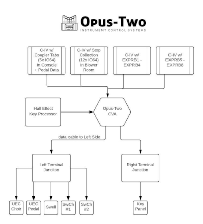
The drawing shown is a block illustration of the various components of the Opus-Two control system for the Midmer-Losh organ. This is a “logical diagram” and is taken directly from the documentation book for the organ. This allows a technician to visualize the flow of data from the various components. A common question relates to how the various panels “talk” to one another. The panels that are listed “above’ the C-IV in the diagram sit idle until the CVA requests their data. The CVA sends the request over the PipeBus port, and the panels reply with the state of the attached IO cards. The CVA can poll them as often as is necessary as the communication occurs at an extremely high speed. Each panel is polled every time a data frame is sent to the chamber controllers, ensuring they have the most accurate information available. If a sub-controller doesn’t answer in time, it’s previous response is allowed to ‘fill the gap’ until it comes back online (this is helpful for panels that run from a generator and may experience very short power outages).
The addition of a combination action in 2019 was one of the most labor-intensive parts of the project. Additional data collection points were added inside the console to capture piston presses, piston rails were re-wired (re-using original contacts and pistons), and the stop collection panel in the basement was expanded to included every single stop tab in the instrument. Featuring the current-standard CVA combination action (10,000 levels), it is one of the first projects to use the new Nano Controller. From piston press to tab movement is less than 10ms, with absolutely no interruption to the continuous pipe processing.

The combination action panel in the basement where the stop coils are driven. This panel is made up of High Output cards and Nano Controllers. This panel uses “High Output” cards which have extremely advanced on-board current monitoring. A blue LED above every connector indicates that that connector was shut down for an over current condition - one can be seen in the lower left of this photo, which was taken during the troubleshooting phase of the project.